
Regenerative Turbine Pump - Little Pump - Big Head
What is a regenerative turbine pump? How does it operate?
What are its head and capacity ranges? How does it differ from
a centrifugal pump? These and other questions are answered!
For Handling Liquid,
regenerative turbine pumps fill a need between centrifugal and positive displacement designs. They combine high discharge pressure of displacement types with the flexible operation of centrifugals. They are a low-capacity high-head type used on heads up to 2300 ft (700 m) and in capacities up to 150 gpm (34 m3/hr). Regenerative turbine pumps are known by several names, such as vortex, peripheral and regenerative. None of these give a true description of the pump, but regenerative turbine is the nearest. Several types of rotating pumps have been called "turbine". Among them are the horizontal-shaft diffuser type and vertical-shaft deep-well centrifugal. The operation of the small pump with a big head, the regenerative turbine pump, is discussed here.
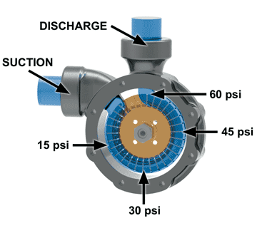
Fig 1. - Pressure produced by a regenerative turbine pump increases continuously from suction to discharge

Fig 2. - Cross section of a regenerative turbine pump. Vanes cut in the impeller's rim revolve in an annular channel where pressure is produced to a helical rotation of the liquid.
Regenerative Turbine Pump Design
Fig. 1 and 2 show cross sections through a regenerative turbine pump. Fig. 2 shows the general construction to be quite like many small centrifugal designs. Its shaft, often made of stainless steel, is supported by two ball bearings. The impeller is overhung, a common construction for centrifugal pumps. The pump is generally supplied with a mechanical seal as standard. The chief difference between centrifugal and regenerative turbine pumps is in the impeller. In the regenerative turbine pump a double row of vanes is cut in the impeller's rim, Fig. 3. These vanes rotate in a channel, Fig. 2. Liquid flows in at the suction, Fig. 1, and is picked up by the impeller's vanes. After making nearly one revolution in the annular channel, the fluid has a high velocity that sends it out the discharge. Liquid entering a centrifugal pump's impeller can pass between its vanes but once. It has energy added to it only while going from the impeller's eye to its rim. In a regenerative turbine pump, liquid recirculates between the impeller's vanes, as in Fig. 4. Because of this action the fluid flows in a path like a screw thread (helical) as it is carried forward. Consequently, energy is added to the fluid in a regenerative motion by the impeller's vanes as it travels from suction to discharge. This regenerative action has the same effect as multistaging in a centrifugal pump. In a multistage centrifugal, the fluid's pressure is the result of energy added in the different stages. In the same way, in a regenerative turbine pump, pressure at its discharge is the result of energy added to the fluid by a number of impeller vanes.
Fig. 3 - Regenerative turbine pump's impeller showing radial vanes on each side of its rim
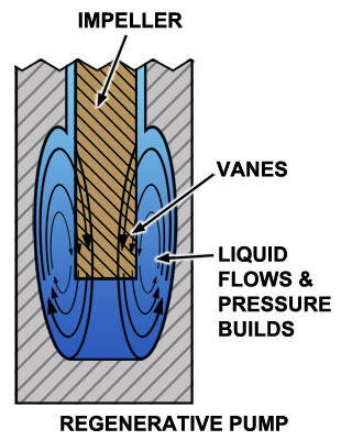
Fig. 4 - As impeller carries it forward, fluid circulates between the vanes as shown
Flow in the Impeller
Recirculation of liquid between the vanes of a regenerative turbine pump occurs a number of times between suction and discharge. The path of fluid travel can be thought of as an extended helical spring bent in a circle until its ends nearly touch. When the pump operates under low heads, space between the helical coils increases. On high heads the helix closes. That is, the fluid circulates more times in its travel from suction to discharge.
Regenerative Pump Construction
In Fig. 2 the pump has a vertical split case. By removing bolts B, cover C and liner L1 can be taken off to inspect or remove the impeller. To keep liquid flow small from high to low-pressure areas in the pump, the impeller has close clearance between liners L1 and L2.
Pressure on the Impeller
About one-half discharge pressure exists around the impeller's hub, which is the pressure on the mechanical seal. Holes H through the impeller prevent unbalanced pressures on it and end thrust on the bearings. A small bypass flow also occurs across the sealing surfaces between the discharge and suction, Fig. 1. Wear on these sealing surfaces increases the clearances and the bypass flow. The same thing happens at the sealing rings of centrifugal pumps. This wear reduces pump capacity greatly when operating at a high head. Most failures of regenerative turbine pumps are caused by this wear at the sealing surfaces. A study of the causes of wear belongs in a separate article where it can be discussed at length. However to prevent serious wear, don't let the impeller touch liners L1 and L2, Fig. 2 and be sure pumped liquid is free of abrasive material. Roth regenerative turbine pumps with patented self-centering impellers greatly reduce the wear problem.
Discharge Pressure
A regenerative turbine pump can develop several times the discharge pressure of a centrifugal type having equal impeller diameter and speed. This pressure increases rim as indicated in Fig. 1.
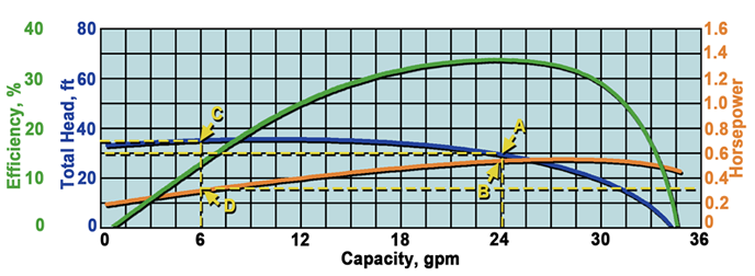
Fig. 5 - Power needed to drive a medium-head centrifugal pump decreases as the discharge head increases as indicated by the horsepower and head-capacity curves
Pump Operation
Power required to drive a centrifugal pump decreases as operating head increases, as indicated by the horsepower curve, Fig. 5. At 24 gpm, total head is 30 ft, point A, and power about 0.6 hp, point B. If we throttle the pump to reduce its capacity to 6 gpm, head increases to 36 ft, point C, and power drops to about 0.35 hp, point D. Fig. 6 shows how a comparable regenerative turbine pump performs. At 24 gpm its discharge head is about 55 ft, point E and requires about 0.7 hp to drive it, point F. If we throttle the pump down to 6 gpm its head goes to 124 ft, point G, and its power to 1.4 hp, point H. So, select the driving motor for the highest head the turbine pump will have to develop.
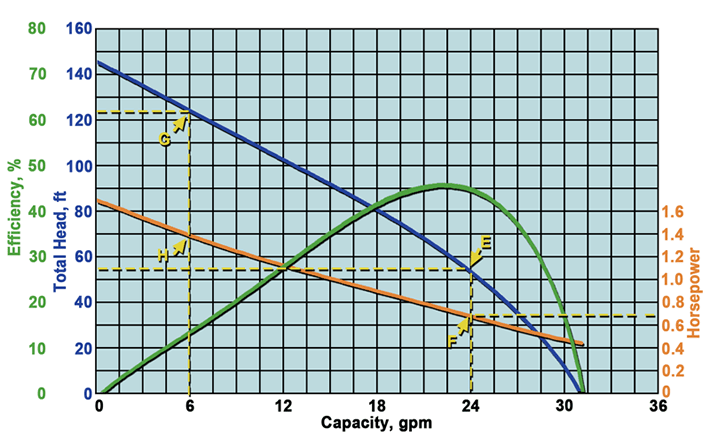
Fig. 6 - If a regenerative turbine pump is throttled to reduce its output, discharge pressure and power input increase
Test Curves
The curves, Figures 5 and 6 are from tests. The centrifugal pump had a 6-in. impeller and the regenerative turbine a 4.25-in. impeller, each running 1750 rpm. Fig. 6 shows the high head obtained with a small diameter impeller. It also shows the pump's wide operating range. This range is desirable on many applications where the head may vary greatly or is hard to find. In Fig. 5, the centrifugal pump operates most efficiently at 30-ft head and 24-gpm. The regenerative turbine pump develops 55-ft head at 24 gpm. If the head increased 5 or 6 ft, the centrifugal pump could not discharge. On the turbine pump this increase in head would cause only a slight decrease in capacity with a small increase in power. Power for a regenerative turbine pump reaches a maximum at shutoff where it is the lowest on a centrifugal pump. So regenerative turbine pumps should not be operated against a closed discharge, unless a pressure relief valve is used. Install a pressure gauge on the pump's discharge, observe the manufacturer's pressure limits and you'll increase the pump's life.
Download the PDF version of Regenerative Turbine Pump - Little Pump - Big Head
Related Products
regenerative pumps product lines
Roth Pump offers a variety of of both chemical & industrial pumps for improving the operation and efficiency of commercial systems
-
Chemical Pumps
Overview of available regenerative turbine chemical pumps
-
Industrial Pumps
Overview of available industrial regenerative turbine pumps